
Pathway First
Confirm routes, entries, capacity and access before selecting the media or electronics.
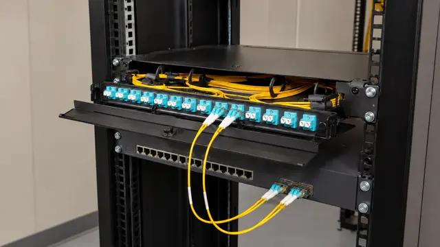
Multi-Building Infrastructure Guide
Multi-building cabling is more than a cable-length exercise. The plan must account for building entry points, pathways, equipment rooms, distance, electrical isolation, bandwidth, service access and the systems that depend on each link.
A documented backbone gives cameras, access devices, wireless links, business networks and future expansion a predictable foundation. Fiber is often considered between buildings because it supports distance and bandwidth without carrying electrical current, but the exact design still depends on the property.
Confirm routes, entries, capacity and access before selecting the media or electronics.
Map the main room, distribution points, buildings, fibers, ports and dependent systems.
Specify appropriate acceptance testing and preserve results with the closeout records.
Reserve practical strands, rack space, power and pathway capacity for expected growth.
The plan should identify where services originate, how each building connects, which systems share the backbone and what happens if a link or equipment room is unavailable. It should also define ownership at every handoff between pathways, cabling, network electronics and connected devices.
Fiber type, strand count and topology are important, but they follow the operational requirements. A small office pair, resort campus, condominium complex and industrial property may need different capacity, resilience and service strategies.
List each structure, current network room, camera, access, wireless and business-network dependency.
Verify conduit, handholes, aerial routes, building entrances, firestopping and physical access.
Estimate present traffic, planned growth, strand use and whether alternate paths or spare links are justified.
Plan racks, enclosures, patching, power, grounding coordination, cooling and service clearance.
Define link tests, labels, as-built drawings, port records and ownership for future support.
Measure the actual route, not a straight-line estimate, and include service loops and terminations.
Choose the exact cable and optics around distance, application, pathway and lifecycle requirements.
Compare star, ring or other supported arrangements against operations, failure impact and maintainability.
Document active, spare and reserved capacity without assuming every future use is known.
Address underground, aerial, wet-location, indoor transition and physical-protection requirements.
Confirm rack space, power, cooling, security, patching and technician access.
Specify insertion-loss, polarity, length or other appropriate tests for the installed link.
Use consistent identifiers from the site map through panels, ports, fibers and connected equipment.
Assign responsibility for trenching, conduit, handholes, restoration, permits and building penetrations.
Define optics, switches, uplink speeds, redundancy, management and power requirements.
Coordinate applicable telecommunications infrastructure with the project electrical and code responsibilities.
Identify rated assemblies, entrance facilities and indoor/outdoor cable transitions.
Deliver test results, route drawings, strand assignments, equipment settings and warranties that actually apply.
Trace source equipment, panels, splices, enclosures and building distribution points.
Confirm type, strand count, connector condition, labeling and supported optics rather than relying on jacket color alone.
Use appropriate instruments and reference methods to verify the installed links.
Check active utilization, link speeds, spare strands, rack resources and the systems being added.
Connect guest, operations, parking and service buildings through controlled distribution points.
Support towers, gates, garages, amenities and management facilities across the property.
Reach yards, remote buildings, docks and security devices over long property distances.
Plan documented building links around IT, facilities and occupied operations.
Separate shared backbone responsibilities from tenant and system-specific connections.
Daytona-area resorts, condominium communities, commercial campuses and industrial properties may place entrances, garages, service buildings and network rooms far apart. Existing pathways and operating schedules often determine what can be implemented without unnecessary disruption.
Coastal or exposed pathway segments also deserve material and enclosure review, but environmental assumptions should not replace an on-site assessment. Building conditions, route access and serviceability remain property-specific.
Install, terminate, test and document the selected fiber links.
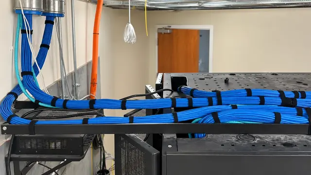
Build labeled horizontal and backbone pathways inside each building.
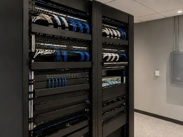
Configure switching, uplinks, segmentation and managed connectivity.
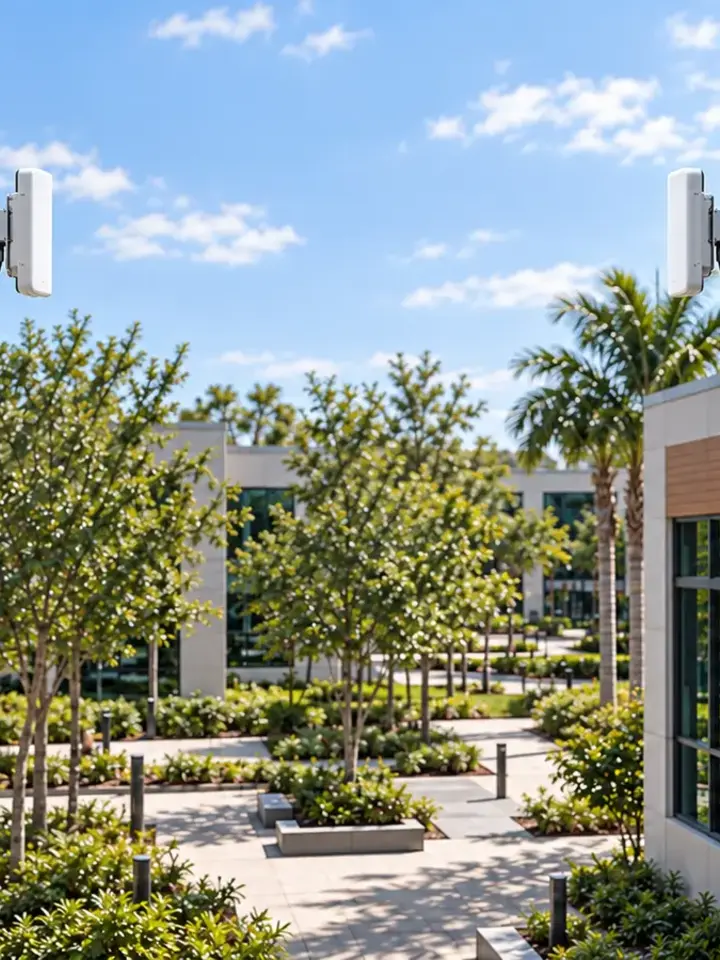
Evaluate wireless links where pathways are unavailable or as a planned alternate.

Connect remote cameras through the documented distribution design.
Support controlled openings across distributed facilities.
Connect infrastructure decisions to occupied hospitality operations.
Coordinate towers, garages, gates and management spaces.
Review exposed transitions, enclosures and service access.
Assess whether the existing backbone supports modernization.
Record buildings, pathways, rooms, distances and dependent systems.
Set capacity, resilience, security, growth and operating constraints.
Verify constructability, entries, racks, power, cooling and access.
Document media, strands, optics, labels and acceptance criteria.
Test every link and deliver accurate as-built records for support.
Data Pro Communications supports commercial security camera and related low-voltage projects under FL License #EC13016138. Project scope, permitting responsibilities and coordination with other trades depend on the property and accepted work.
FAQ
Fiber supports long distances and high bandwidth without carrying electrical current between structures. The selected fiber, optics, pathway and topology still need to match the site's requirements.
The count should reflect active links, redundancy, planned systems, practical spares and the cost of returning to the pathway. There is no universal strand count for every property.
A direct star can simplify fault isolation, but pathways, distances, resilience and property layout may support a different documented topology. The decision should be made at the site level.
They can share properly designed infrastructure when capacity, segmentation, security, availability and ownership are addressed. Shared fiber does not mean every system should share the same logical network.
Confirm route, fiber type, strands, connectors, splices, patching, optics, labels and physical condition, then perform the tests appropriate to the intended application.
Wireless may be useful when a physical pathway is impractical, as a temporary connection or as a planned alternate. Clear path, mounting, spectrum conditions, capacity, power and support access must be reviewed.
Show buildings, pathways, entrances, equipment rooms, panels, cable and fiber identifiers, strand or port assignments, distances, splices and the systems served.
Coordinate conduit size, pathway routes, handholes, rack space, power, cooling, spare fiber and accessible service loops before finishes make changes expensive.
Keep the specified acceptance results, instrument and reference information where applicable, cable identifiers, endpoint records, exceptions and the final as-built route documentation.
Facility operations, IT, property management, construction stakeholders and the teams responsible for cameras, access or other connected systems should identify requirements and ownership together.
Bring available site plans, pathway records, building lists, network-room information and expansion goals. Data Pro Communications can help organize the physical and network dependencies into a survey-based infrastructure plan.