
Endpoints Confirmed First
Transceivers, switches, speeds and connector requirements are identified before selecting the installed fiber assembly.
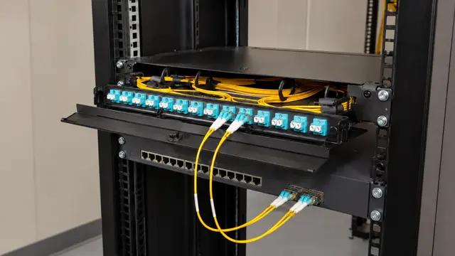
HIGH-CAPACITY LINKS BETWEEN COMMERCIAL SPACES
Fiber can connect buildings, floors, equipment rooms and distant technology zones where copper reach, electrical isolation or bandwidth needs make an optical backbone appropriate. Data Pro Communications plans the pathway, fiber type, strand capacity, terminations and test documentation as one system.
A useful scope begins with the equipment at both ends and the route between them. Connector choices, enclosure locations and future capacity should support the customer's actual network rather than an unspecified fiber run.
Transceivers, switches, speeds and connector requirements are identified before selecting the installed fiber assembly.
Conduit, innerduct, risers, outdoor transitions and building entries are reviewed before pulling cable.
Active needs and reasonable future growth shape the strand count and termination layout.
Panels, splice locations and slack storage are positioned for future inspection and change work.
Completed links are documented with appropriate test results and endpoint labels.
A fiber backbone includes more than cable. The design needs compatible optics, connector and polishing types, patching, enclosures, bend management and a clear plan for each strand. Mismatches can leave a clean installation unable to support the intended equipment.
Route conditions also matter. Indoor risers, underground conduit and exterior building transitions create different handling and protection needs. Final media selection depends on distance, speed, pathway and the customer's equipment strategy.
Connect detached structures or property zones with an optical route suited to the surveyed pathway.
Distribute network capacity between main and intermediate equipment rooms across floors or wings.
Organize connectors, panels and patch cords around supported equipment and service access.
Inspect identification, endpoint condition and testable strands before assigning inherited fiber to a new use.
Reserve practical capacity when the route is costly or disruptive to revisit.
Coordinate single-mode or multimode fiber, wavelengths, speeds, connectors and transceivers at both ends.
Verify conduit continuity, capacity, pull access, bends and building-entry treatment.
Protect panels and splices from unsuitable heat, moisture, dust and physical access.
Define labeling and test deliverables so the owner can identify usable strands after handoff.
Resorts and large managed properties may need to connect separate guest, administrative, parking or service buildings. The best route depends on existing conduit, equipment-room placement and the systems sharing the backbone.
Oceanfront condominium towers can use fiber between main and intermediate rooms to support distributed network, camera and access infrastructure. Riser access and renovation phasing should be understood before termination locations are fixed.
Warehouses, industrial sites and commercial campuses may place gates, yards or remote equipment rooms beyond copper reach. Fiber can provide a physical backbone where the construction path and endpoint equipment make it practical.
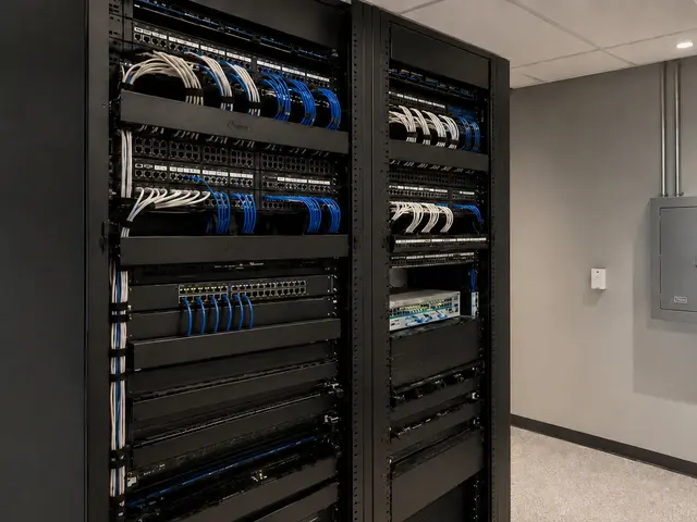
Match fiber uplinks with switches, racks, topology and management responsibilities.
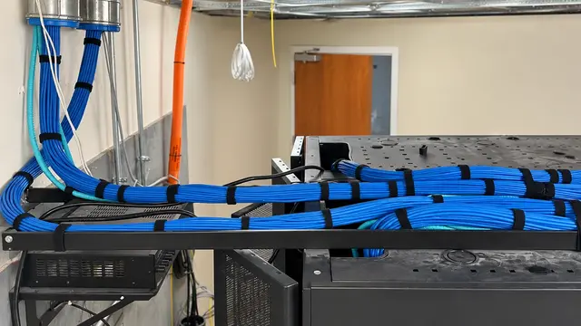
Distribute copper from fiber-fed equipment rooms to local endpoints.
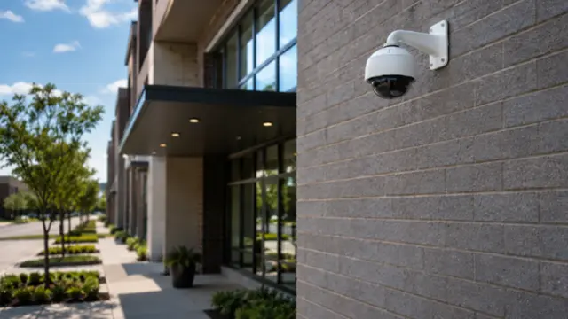
Carry camera traffic between distant buildings or equipment zones when the design calls for optical transport.
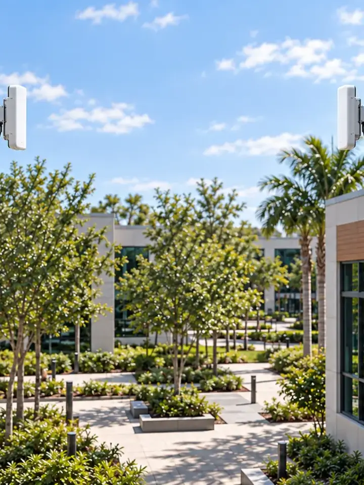
Compare a surveyed wireless bridge with a physical fiber route when site access is constrained.
Confirm locations, equipment interfaces, speed and active-strand needs.
Review conduit, risers, entries, pull points and environmental transitions.
Place the selected fiber, manage slack and complete labeled panels or enclosures.
Document the installed strands and provide results tied to the endpoint identifiers.
FAQ
Fiber often connects buildings, floors, remote equipment rooms and high-capacity network backbones. It can carry camera, access, wireless and business-network traffic when the endpoint equipment and design support it.
Selection depends on distance, speed, installed plant, optics, connector strategy and future network plans. The choice should be coordinated end to end rather than made from distance alone.
Potentially, after the strands, connectors, route and test results are identified. Compatibility with the planned optics and patching must also be confirmed.
The pathway must protect the cable and provide suitable pull access, but the exact construction can vary. Existing conduit should be checked for continuity, capacity, bends and building-entry conditions.
The accepted scope may include strand identification, loss measurements and other appropriate results tied to both endpoints. Deliverables should be defined before installation.
Connectors that look similar may not be compatible. The patch panels, jumpers, optics and installed terminations must use a coordinated interface.
Yes, when the design includes suitable field switching, power, enclosures and a physical route. Fiber carries data, so local equipment still needs an appropriate power plan.
Spare strands can be valuable on routes that are difficult to reopen. The quantity should reflect expected growth, pathway cost, termination space and the owner's network strategy.
Often, subject to route access, work windows and protection of active services. Building entry, equipment-room access and any construction coordination should be planned in advance.
Provide endpoint locations, target speeds, equipment information, known pathways, building separation and any existing fiber records. Field verification is still required before final design.
Share the building layout, endpoint rooms, known conduit and target network speed. Data Pro Communications can review the practical fiber pathway and termination scope.